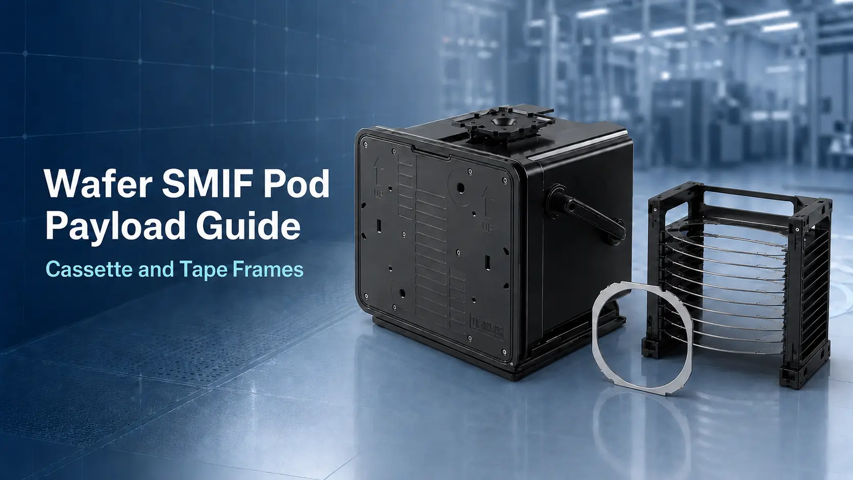
Wafer SMIF Pod Payload Guide: Cassette, Substrate, and Tape Frame Compatibility
A wafer SMIF pod is commonly associated with enclosed, cassette-based wafer handling through a controlled equipment interface.
However, the term is also used in the market for enclosed carriers developed around different payloads and equipment configurations. Some products hold a wafer cassette, while others may be designed for substrates, tape frames, or process-specific carriers.
These configurations should not be assumed to use the same internal structure.
Before selecting a wafer SMIF pod, start with one practical question:
What will actually be loaded inside the carrier?
A cassette, thin substrate, and dicing tape frame have different dimensions, support points, loading directions, and clearance requirements. The payload should therefore be defined before the pod capacity or internal layout is confirmed.
What Does a Standard Wafer SMIF Pod Usually Hold?
Conventional SMIF systems are generally associated with cassette-based wafer handling.
In this configuration, wafers are held inside a separate cassette. The cassette is placed in an enclosed pod and presented to compatible equipment through a controlled mechanical interface.
The pod and cassette perform different functions:
- The cassette holds and separates the wafers.
- The pod encloses the cassette during storage and transport.
- The equipment interface controls access and transfer.
This basic arrangement should not be confused with a carrier that directly supports individual wafers, substrates, or tape frames.
For non-standard payloads, the product may use a customized enclosed-carrier or FOUP-style structure. The actual door design, internal supports, loading method, and equipment interface must be checked rather than assumed from the product name.
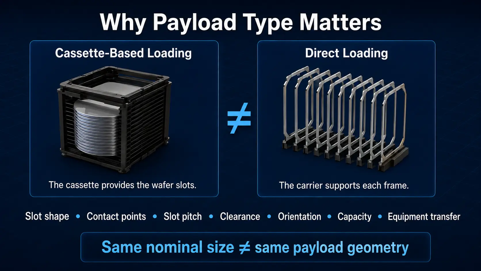
Why Payload Type Matters
The internal design of a carrier depends on the shape and condition of the material being loaded.
A wafer cassette already contains its own wafer slots. A direct-loading carrier, by contrast, must support each substrate or frame inside the pod.
This affects:
- Slot shape
- Contact points
- Slot pitch
- Payload clearance
- Loading orientation
- Capacity
- Equipment transfer method
A “12-inch” or “25-slot” label alone does not define these conditions.
A 12-inch wafer, a cassette for 12-inch wafers, and a 12-inch tape frame do not have the same external dimensions. They also cannot be assumed to use the same support structure.
Wafer Cassette Loading
When a cassette is loaded into a wafer SMIF pod, the cassette itself becomes the main payload.
The following information should be checked:
- Cassette model
- External dimensions
- Supported wafer diameter
- Number of wafer slots
- Cassette orientation
- Base and door clearance
- Equipment-side transfer method
Physical fit is only one part of compatibility.
The cassette must also be positioned correctly when the pod reaches the load port or transfer equipment. A cassette that fits inside the shell may still be unsuitable if its orientation, base geometry, or transfer position does not match the equipment.
For an existing production line, use the cassette model and equipment interface drawing as the primary references.
Direct Substrate Loading
Some enclosed carriers are developed to hold substrates directly rather than enclosing a conventional wafer cassette.
Possible payloads may include:
- Individual wafers
- Thin substrates
- Square substrates
- Process-specific plates
- Other non-standard materials
In these cases, the internal supports are part of the carrier specification.
The supplier needs the actual payload dimensions rather than a general description such as “wafer” or “substrate.”
Important information includes:
- Shape
- Maximum width and length
- Thickness
- Edge condition
- Permitted contact areas
- Areas that must remain free from contact
- Loading direction
- Required quantity
Thin or irregular substrates may need additional support to limit movement inside the carrier. The support design should also avoid contact with active or sensitive surfaces.
Tape Frame Loading
A tape frame or dicing frame holds a wafer on dicing tape. Its overall dimensions are determined by the frame, not only by the wafer diameter.
For example, two frames intended for the same wafer size may have different:
- Maximum outer dimensions
- Minimum outer dimensions
- Frame thicknesses
- Flats or notches
- Positioning holes
- Tape overhang
- Outer profiles
A carrier suitable for one tape frame may therefore be unsuitable for another, even when both are described as 12-inch types.
When a wafer SMIF pod or enclosed carrier is intended for tape frames, the complete frame drawing should be reviewed.
At minimum, provide:
- Maximum outer dimension
- Minimum outer dimension, when applicable
- Inner opening
- Frame thickness
- Flat and notch geometry
- Positioning-hole locations
- Tape overhang
- Loading direction
The support points should hold the frame without contacting the wafer, dicing tape, or other critical areas.
Slot Pitch and Capacity
Capacity should not be confirmed from the slot count alone.
A product described as 25-slot only provides 25 usable positions under a defined payload and internal configuration.
Actual capacity depends on:
- Payload thickness
- Slot pitch
- Required vertical clearance
- Support geometry
- Frame rigidity
- Loading and removal method
For example, a thicker tape frame may require more clearance between positions. Changing the slot pitch may reduce the number of payloads that fit within the same carrier height.
A “25-slot” label is only meaningful after the allowable payload thickness and slot pitch are known.
Before ordering, confirm:
- Nominal slot pitch
- Maximum permitted payload thickness
- Clearance between adjacent payloads
- Required loading tolerance
- Usable capacity for the actual payload
Loading Direction and Contact Points
Loading direction is particularly important for tape frames and non-standard substrates.
The carrier design should define:
- Which edge enters first
- Whether loading is horizontal or vertical
- Where the payload is supported
- How lateral movement is limited
- How the operator or equipment removes the payload
- Which areas must remain untouched
Contact points should not interfere with:
- The wafer surface
- Dicing tape
- Active substrate areas
- Frame positioning features
- Automated gripping areas
For automated loading, the internal position must also match the transfer mechanism on the equipment side.
A payload that fits inside the carrier but cannot be reliably inserted or removed is not a compatible configuration.
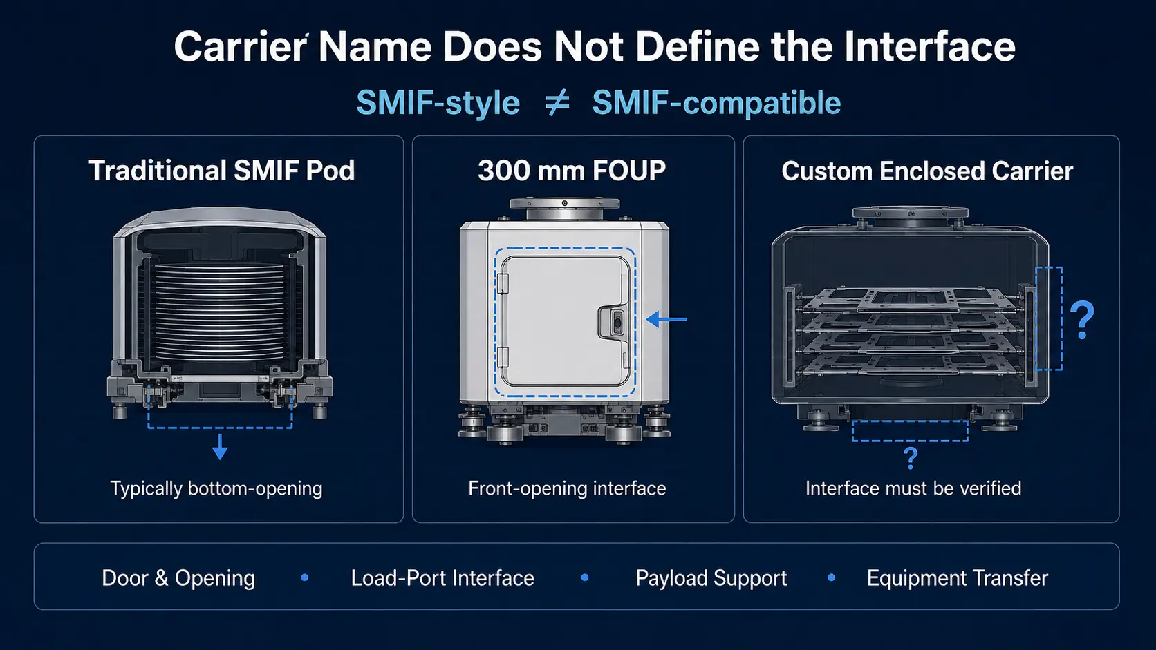
SMIF Pod, FOUP-Style Carrier, or Custom Enclosed Carrier?
Product names are not always used consistently across suppliers.
Traditional SMIF systems are closely associated with cassette-based wafer handling. FOUP systems are more commonly associated with front-opening 300 mm wafer handling.
Tape-frame and non-standard substrate applications may instead use:
- A customized SMIF-style pod
- A FOUP-style enclosed carrier
- A tape frame FOUP
- A process-specific enclosed carrier
The name alone does not confirm the interface.
For 300 mm or tape-frame applications, review:
- Door position
- Opening method
- Load-port interface
- Payload orientation
- Internal support structure
- Equipment transfer method
This distinction is important when replacing an existing product. Two enclosed carriers may have similar dimensions but use different doors, bases, locks, or equipment interfaces.
Equipment Compatibility
A wafer SMIF pod should not be selected only as a storage box.
The carrier may need to work with:
- A load port
- A transfer station
- Process equipment
- Automated transport
- Manual handling tools
- Storage racks or stockers
Prepare the following equipment information:
- Equipment manufacturer
- Model number
- Interface or load-port drawing
- Available clearance
- Door-opening method
- Payload transfer method
- Carrier orientation
- Manual or automated transport conditions
When possible, compare the new carrier with the existing pod, cassette, or tape-frame carrier already used on the line.
Compatibility should be based on drawings and operating conditions rather than a shared product name.
Information to Prepare Before Requesting a Carrier
A supplier cannot determine the internal configuration from “wafer SMIF pod” or “12-inch carrier” alone.
Prepare the information that directly defines the payload:
- Payload type
- Payload drawing
- Maximum and minimum outer dimensions
- Thickness
- Permitted contact points
- Areas that must remain free from contact
- Required quantity
- Slot pitch
- Loading orientation
- Cassette model, when applicable
- Tape frame drawing, when applicable
- Equipment manufacturer and model
- Transfer method
If an existing product is being replaced, also provide:
- Existing product model
- Carrier drawing
- Photographs
- Current loading method
- Physical sample, when available
This information helps determine whether a standard product may be suitable or whether a customized carrier configuration should be considered.
YJ COREVIA Wafer SMIF Pod and Tape Frame Carrier Support
YJ COREVIA provides the TJF-U12-25S, which is presented as a 12-inch Wafer FOUP, Wafer SMIF Pod, and Tape Frame FOUP solution.
According to the product information, the carrier is intended for applications involving 12-inch wafers, thin substrates, square materials, and tape frames. A 25-slot configuration and optional identification functions are also listed.
Because these payloads differ in size and support requirements, suitability should be checked using the actual payload drawing and equipment information.
When discussing an application with YJ COREVIA, provide:
- The material being loaded
- Payload or frame drawing
- Thickness
- Required capacity
- Loading direction
- Existing equipment information
YJ COREVIA can review the supplied information to determine whether the standard product or a customized carrier configuration should be considered.
Summary
A wafer SMIF pod is commonly associated with enclosed, cassette-based wafer handling, but products in the market may also be developed around substrates, tape frames, and other specialized payloads.
These configurations are not automatically interchangeable.
Before selecting a carrier, define whether it will hold:
- A wafer cassette
- Substrates directly
- Tape frames or dicing frames
Then confirm the payload dimensions, thickness, support points, slot pitch, loading direction, capacity, and equipment interface.
Do not rely only on terms such as “12-inch,” “25-slot,” “SMIF Pod,” or “FOUP.” The actual payload drawing and equipment conditions should determine the carrier configuration.
For wafer cassette, thin-substrate, or tape-frame carrier applications, contact YJ COREVIA with your payload drawings and equipment information.
FAQ
1. What does a wafer SMIF pod normally hold?
Traditional SMIF systems normally enclose a wafer cassette. Other products may use customized supports for substrates or tape frames, but the actual configuration must be checked.
2. Can a wafer SMIF pod hold tape frames?
It can when the internal dimensions, supports, slot pitch, contact points, and loading method are designed for the specific frame. A frame drawing is required to evaluate compatibility.
3. Does a 25-slot carrier hold every 25-piece payload?
No. Usable capacity depends on payload thickness, slot pitch, support geometry, and required clearance.
4Is a 12-inch SMIF Pod the same as a 12-inch FOUP?
Not necessarily. The terms may refer to different door positions, interfaces, payloads, and equipment configurations. Review the actual product and interface drawings.