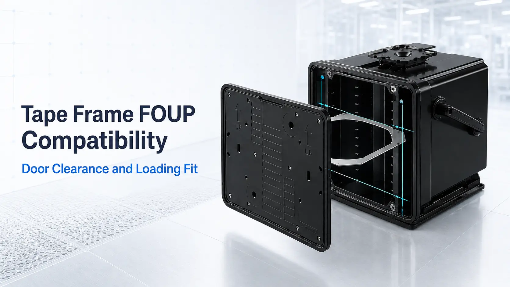
Tape Frame FOUP Compatibility: Door Opening, Internal Clearance, and Equipment Access
A Tape Frame FOUP is an enclosed carrier designed to transport wafers mounted on dicing or film frames.
A standard wafer FOUP supports individual wafers inside its internal slots. A Tape Frame FOUP must instead accommodate the larger outer frame, which changes the required door opening, guide structure, internal clearance, and equipment transfer method.
This is why compatibility cannot be confirmed from wafer diameter, external carrier dimensions, or slot count alone.
A carrier may look large enough from the outside but still be unsuitable if the tape frame cannot pass through the door, move between the guides, or be removed by the equipment.
Tape Frame FOUP and 300 mm Interface Standards
Tape Frame FOUPs are increasingly used in processes involving 300 mm dicing frames and advanced packaging applications.
SEMI published E184 and E185 for interfaces related to 300 mm Tape Frame FOUP systems. These standards help define interface conditions for the carrier and equipment side.
However, the existence of a standard does not mean every Tape Frame FOUP, tape frame, or load port is automatically interchangeable.
Actual compatibility still depends on:
- Tape-frame dimensions
- Door and base design
- Internal supports
- Loading orientation
- Equipment interface
- Transfer method
Do not assume that a carrier complies with a particular standard unless the supplier provides supporting specifications or verification.
Quick Tape Frame FOUP Compatibility Check
| Check | Why It Matters |
|---|---|
| Tape-frame outer profile | Determines whether the complete frame can enter the carrier |
| Clear door opening | External carrier dimensions do not show the actual entry space |
| Usable internal envelope | Shell walls, guides, locks, and supports reduce available space |
| Insertion orientation | The frame may fit in only one approved direction |
| Complete loading path | Door edges or internal structures may cause interference |
| Final support position | The frame must rest without unwanted contact with the wafer or tape |
| Equipment access | The load port or robot must be able to insert and remove the frame |
| Approved frame range | A “12-inch” description does not define one universal frame size |
External Dimensions Are Not Usable Internal Dimensions
FOUP specifications usually list the overall width, depth, and height.
These dimensions include the shell, door, locks, guides, ribs, base structures, and automation features. None of these spaces are fully available to the payload.
The usable interior is therefore smaller than the published external dimensions.
This matters because the complete tape frame is larger than the wafer mounted on it. A product described as “12-inch compatible” may refer to the wafer size or product category, not a universal tape-frame outer dimension.
For example, a 400 mm-class frame may appear compatible with the carrier’s overall footprint. It still needs to clear the actual door opening and internal guide structure.
Check the Clear Door Opening
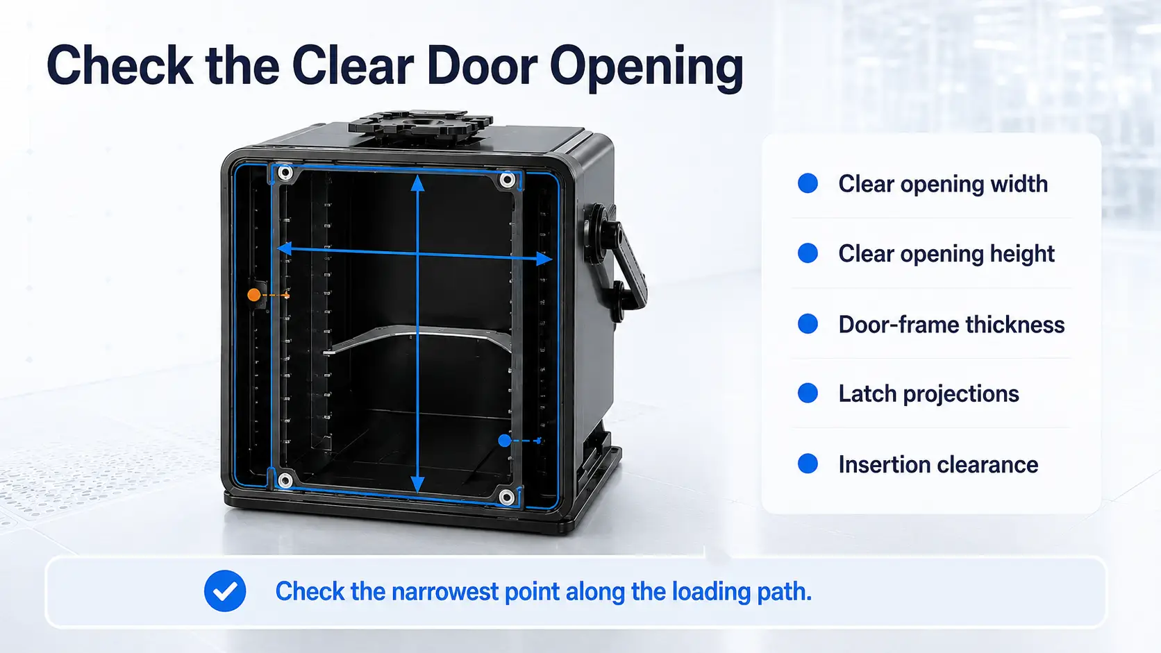
The clear door opening is the first dimension to check.
Use the unobstructed opening after the door is fully open. Do not substitute:
- The external carrier width
- The door-panel dimensions
- The outside frame of the opening
The review should include:
- Clear opening width
- Clear opening height
- Door-frame thickness
- Lock or latch projections
- Available insertion clearance
The door opening may not be the narrowest point. Internal guides, support tabs, locks, or structural ribs may further restrict the loading path.
Review the Complete Loading Path
A frame does not move directly from the door into its final position without passing other structures.
A practical compatibility review should answer three questions:
- Can the frame pass through the opening?
- Can it move through the carrier without interference?
- Can it rest in the final position with sufficient clearance?
All three conditions must be satisfied.
Potential interference points include:
- Door edges
- Locking components
- Slot entrances
- Internal guides
- Support tabs
- Base structures
- Adjacent frames
A frame that passes through the door but cannot move into the slot area is not compatible.
Frame Orientation Must Match the Handling Method
Tape frames may include flats, notches, holes, tabs, or other non-circular features.
Because of this, a frame may fit in one direction but not another.
Rotating or tilting the frame may appear to solve the clearance problem, but this is only practical when the movement is part of the approved handling method. A frame that requires manual tilting may not be suitable for an automated line.
The selected orientation must work with:
- Internal guides
- Final support position
- Equipment transfer direction
- Robot or operator access
Compatibility should be based on the complete insertion and removal movement, not only the frame’s shortest dimension.
Use the Complete Tape-Frame Drawing
The term “12-inch tape frame” does not define a single outer size.
Frames used with the same wafer diameter may differ in:
- Maximum outer dimension
- Shorter outer dimension
- Thickness
- Flats and notches
- Positioning holes
- Tape dimensions
- Outer profile
A dimensioned drawing should show:
- Maximum and minimum outer dimensions
- Frame thickness
- Outer profile
- Tape overhang
- Positioning features
- Intended loading direction
A photograph can help identify the frame, but it cannot replace a drawing for clearance analysis.
If an existing frame is customized or poorly documented, a physical sample may also be needed.
Internal Clearance and Support Position
Passing through the door does not guarantee that the frame will fit correctly inside the FOUP.
The loaded frame needs suitable clearance around its outer edge, tape overhang, door-side components, internal walls, and neighbouring positions.
The support area also matters. Guides should contact suitable rigid parts of the frame without creating unintended contact with the wafer, dicing tape, or sensitive surfaces.
Manual and automated loading may require different working spaces. An automated system may need additional clearance for the robot, gripper, sensors, and positioning tolerance.
A frame that fits with almost no clearance may still cause unstable loading or removal.
Slot Count Is Only a Nominal Capacity
A Tape Frame FOUP may be listed as a 13-slot or 25-slot carrier.
This number does not confirm that every tape-frame design can use all listed positions.
The practical capacity may change with:
- Frame thickness
- Outer profile
- Tape overhang
- Internal spacing
- Required handling clearance
Door fit, internal fit, and usable capacity should be treated as separate checks.
A 25-slot carrier may accept the frame through its door but still lose usable positions if the frame requires more space than the original slot configuration allows.
Equipment Access Is Part of Compatibility
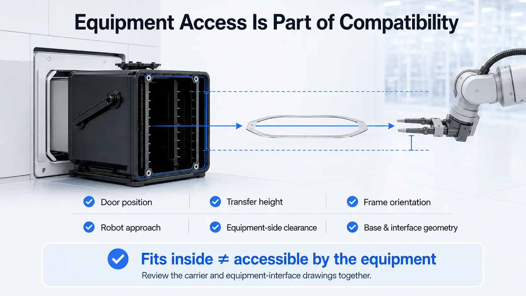
A Tape Frame FOUP may need to connect with a load port, EFEM, stocker, or process tool.
The equipment must be able to access the frame in the same orientation used inside the carrier.
Important points include:
- Door position
- Transfer height
- Frame orientation
- Robot or gripper approach
- Equipment-side clearance
- Base and interface geometry
A frame can fit inside the FOUP but remain unusable if the equipment cannot remove it in the required direction.
For this reason, the carrier drawing and equipment-interface drawing should be reviewed together.
YJ COREVIA Tape Frame FOUP Review
YJ COREVIA provides the TJF-U12-25S, presented as a 12-inch Wafer FOUP, Wafer SMIF Pod, and Tape Frame FOUP solution.
The published product information describes a 25-slot configuration and tape-frame-related applications.
However, the public specifications do not currently define:
- Approved tape-frame dimensions
- Clear door-opening size
- Maximum frame thickness
- Usable internal dimensions
- Slot pitch
- Approved frame models
The external dimensions alone should therefore not be used to confirm compatibility with a specific tape frame.
For a practical review, provide YJ COREVIA with:
- The tape-frame drawing
- Frame thickness
- Loading orientation
- Required capacity
- Equipment model
- Interface drawing, when available
Compatibility should be discussed case by case using the actual frame and equipment information.
Summary
Tape Frame FOUP compatibility depends on more than the wafer size or carrier footprint.
The frame must be able to:
- Pass through the clear door opening
- Move along the complete loading path
- Fit within the usable internal space
- Rest on the intended supports
- Be inserted and removed by the equipment
A carrier may appear large enough externally but still be unsuitable because of its door, locks, guides, or equipment-access conditions.
Use the actual tape-frame drawing, carrier interior, and equipment-interface information before confirming compatibility.
Contact YJ COREVIA with your frame and equipment drawings for a case-by-case Tape Frame FOUP review.
FAQ
1. Can external FOUP dimensions confirm tape-frame compatibility?
No. External dimensions include the shell, door, guides, locks, and other structures. The clear opening and usable internal space are more important.
2. Can a tape frame be inserted at an angle?
Only when angled insertion is part of the approved operating method and can be performed reliably by the operator or equipment.
3. Does a 25-slot FOUP hold every tape-frame design?
No. Usable capacity depends on frame thickness, profile, internal spacing, and handling clearance.