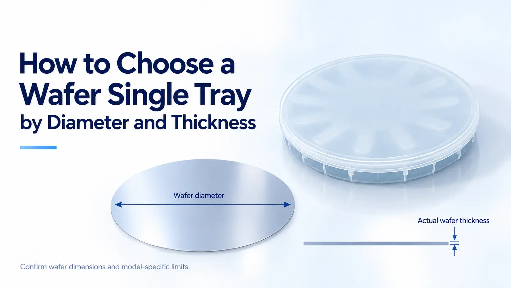
How to Choose a Wafer Single Tray by Diameter and Thickness
Choosing a wafer single tray starts with wafer diameter, but the size label does not confirm a complete fit. Wafer thickness, surface features, warpage, and the tray’s internal support design also need to be checked.
A product’s listed height is not its allowable wafer thickness. To select a suitable model, match the wafer size first, then confirm how the wafer sits inside the tray and whether the lid and handling tools have enough clearance.
This guide explains those checks using YJ COREVIA’s TJF-O series as product examples.
Start with the Actual Wafer Specification
1. Nominal Size and Actual Diameter
A nominal size such as 6, 8, or 12 inches helps identify a candidate product. For fit confirmation, provide the actual wafer diameter and its tolerance from the wafer specification.
Do not substitute the tray’s outside diameter or width for the space available to the wafer. Internal supports, walls, and locating features affect that space.
If the wafer has a nonstandard outline or dimensions, include a drawing rather than relying on the nominal size alone.
2. Individual Wafer or Frame-Mounted Wafer
Confirm the payload before reviewing tray dimensions.
An individual wafer and a wafer mounted on a frame require different support arrangements. For a frame-mounted wafer, the relevant dimensions include the frame outline and the thickness of the complete assembly.
A tray intended for an individual 8-inch wafer should not be assumed to accommodate an 8-inch wafer mounted on a frame.
Understand Which Dimensions Matter
Several dimensions appear in a fit review, and each answers a different question.
| Dimension | What It Describes | How to Use It |
|---|---|---|
| Wafer diameter | The actual wafer size and specified tolerance | Identify a candidate model and confirm its positioning features |
| Wafer thickness | The thickness of the wafer being loaded | Check compatibility with the support and retention design |
| Listed product dimensions | The dimensions published for the tray or enclosure | Plan storage space and outer packaging; do not treat them as internal clearance |
| Usable internal clearance | The space available around the supported wafer | Check interference with the lid, walls, and other internal features |
| Tool clearance | The space needed by the intended handling tool | Confirm that the wafer can be loaded and retrieved correctly |
Review these dimensions together to confirm both wafer fit and handling access.
Why Product Height Is Not Allowable Wafer Thickness
The listed height describes a product dimension. It does not show how much space remains above a wafer after the wafer rests on its supports.
That space depends on the internal design, including the support height, lid profile, and any retention features. External dimensions alone are not enough to determine usable internal clearance. Request the relevant internal dimensions or a drawing to confirm fit.
For example, YJ COREVIA lists the following product dimensions:
- TJF-O6: Ø164 × 21(H) mm, PP.
- TJF-O8: 212(L) × 212(W) × 11.6(H) mm, PC.
- TJF-O12: 348(L) × 338(W) × 50(H) mm, PC.
These figures help identify the products and plan packaging. They do not specify the accepted wafer thickness range or show that the tallest enclosure provides the most suitable support.
See the official specifications for TJF-O6, TJF-O8, and TJF-O12 before requesting fit confirmation.
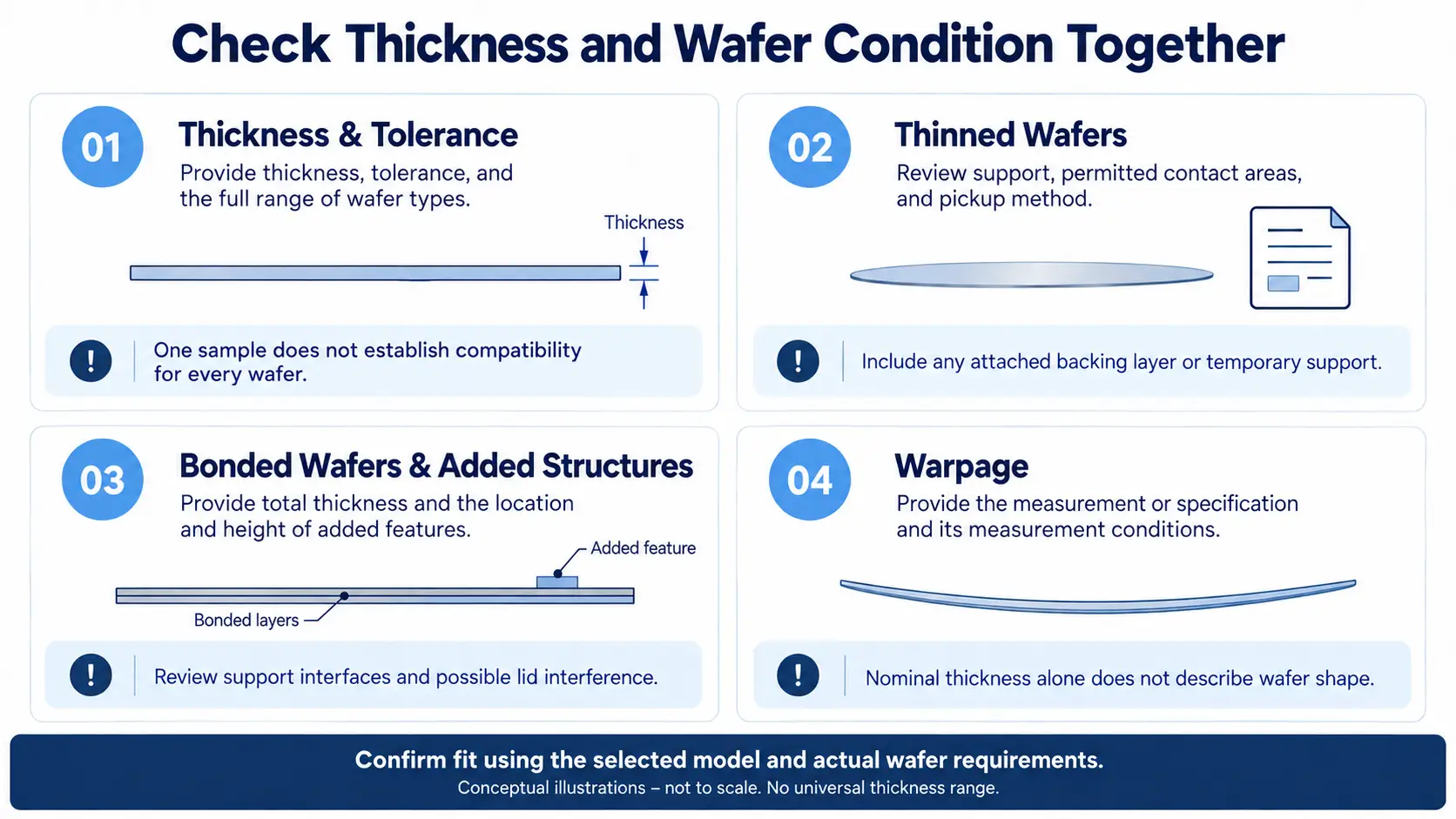
Check Thickness and Wafer Condition Together
1. Thickness and Tolerance
Provide the wafer thickness and its specified tolerance. If one tray will be used for several wafer types, identify the full range that needs to be accommodated.
A tray evaluated with one sample should not automatically be approved for every wafer of the same diameter. A change in thickness may affect support, retention, or clearance.
There is no universal thickness range that can be assigned to all wafer single trays. Use the selected model’s design information and the actual wafer requirements.
2. Thinned Wafers
For thinned wafers, review the support arrangement and handling method specifically. Compatibility with a thicker wafer does not establish compatibility with a thinner one.
Describe the permitted contact areas and how the wafer will be picked up. If a backing layer or temporary support remains attached, include it in the payload information.
3. Bonded Wafers and Added Structures
For a bonded assembly, provide its total thickness. For raised structures or attached components, provide their location and height as well.
The supplier needs enough information to review both the support interface and possible lid interference. A single thickness value may not describe all relevant features.
4. Warpage
If warpage is relevant, provide the available measurement or specification and its measurement conditions.
Nominal thickness alone does not describe the wafer’s shape. Review how that shape interacts with the tray’s support and clearance rather than assuming a flat-wafer fit applies.
Review Contact Locations and Retrieval Access
1. Permitted Contact Areas
Identify which wafer areas may contact the tray: the edge, backside, or other specified regions. Also identify areas that must remain untouched.
Do not assume a tray provides edge-only support without reviewing its design. Ask for the relevant support information when contact restrictions are part of the process requirements.
2. Lid Clearance
Check whether closing the tray introduces contact with the wafer or its surface features. If lid contact is part of the intended retention design, confirm that the contact location and loading are acceptable for the wafer.
Successful closure alone does not demonstrate compatibility.
3. Handling Tool Access
State how the wafer will be loaded and removed. Tweezers, vacuum tools, and other handling methods may require different access spaces.
Review whether the tool can reach the intended pickup location without interference from the tray wall or supports. This is especially useful when replacing an existing tray with a different enclosure design.
Information to Send for a Fit Review
A drawing and a short specification sheet can reduce repeated questions during model selection.
| Information | Details to Include |
|---|---|
| Wafer dimensions | Actual diameter, thickness, and specified tolerances |
| Wafer condition | Thinned, bonded, taped, or otherwise modified |
| Surface features | Location and height of structures that may affect clearance |
| Warpage | Available specification or measurements, where relevant |
| Contact restrictions | Permitted support areas and prohibited contact areas |
| Handling method | Tool type, pickup location, and required access |
| Scope of use | Whether one wafer specification or several variants must fit |
Use consistent units. If the wafer drawing gives thickness in micrometers and the tray information uses millimeters, clearly label each value to avoid confusion.
Evaluate the Candidate Tray Before Volume Purchasing
Follow the facility’s procedures and use a suitable test wafer to evaluate the tray with the intended handling method.
Check that the wafer seats as expected, the support contacts are permitted, and the tool can load and retrieve it. Review lid closure and any intended retention contact.
If the tray must accommodate a specified range of wafers, define which representative samples are needed to evaluate that range. Record the wafer specification, tray model, and result so the evaluation can be traced.
A fit evaluation does not replace shipping, ESD, or cleanliness qualification. Those requirements need their own acceptance criteria.
Contact YJ COREVIA for Wafer Single Tray Selection
For a model recommendation or a volume purchasing inquiry, contact us with the wafer diameter, thickness, condition, and required quantity.
Include drawings showing surface features and contact restrictions where available. For replacement projects, provide the current tray details and any loading or retrieval issues to address.
The inquiry can cover candidate models, sample evaluation, pricing, and lead time. Special dimensions are subject to feasibility review.
Conclusion
Wafer diameter identifies a starting point for tray selection. Thickness, wafer condition, support locations, and handling access determine whether that model fits the application.
Use published product dimensions for product identification and packaging planning. Confirm internal fit through the relevant design information and sample evaluation before committing to volume purchasing.
For the broader overview of applications, materials, and product sizes, read What Is a Wafer Single Tray? Uses, Sizes, and Selection Guide.
Frequently Asked Questions
1. Does Matching the Wafer Diameter Guarantee a Suitable Fit?
No. Diameter identifies a candidate model, but wafer thickness, surface features, support locations, and handling access also affect compatibility. Confirm these details before ordering.
2. Can I Use the Listed Tray Height as the Maximum Wafer Thickness?
No. Listed product height does not describe the clearance available around the supported wafer. Internal supports, the lid profile, and retention features affect that space. Request the accepted thickness range or relevant internal dimensions for the selected model.
3. Can One Tray Accommodate Wafers with Different Thicknesses?
Possibly, depending on the tray design and the required thickness range. Provide the minimum and maximum thickness, along with any differences in wafer condition. Evaluate representative samples before approving the tray for the full range.
4. How Should I Select a Tray for a Thinned or Bonded Wafer?
Provide the actual wafer or assembly thickness, permitted contact areas, and handling method. Include details of any backing layer, raised structures, or relevant warpage. Compatibility with a conventional wafer of the same diameter does not confirm suitability for a thinned or bonded wafer.